Wheel Offset Calculator: Backspacing & Clearance
Use this wheel offset calculator to compare wheel dimensions, convert offset to backspacing, and estimate wheel-position changes relevant to inner suspension and outer fender clearance.
Wheel Edge Movement Summary
The new inner nominal wheel edge extends 22.7 mm farther inboard. This would reduce wheel-edge clearance to a fixed suspension-side reference by the same amount before accounting for tire width, shoulder bulge, or vehicle geometry.
The outer nominal wheel edge extends 2.7 mm farther toward the fender side.
*Note: Position changes are calculated from nominal bead-seat width. Actual physical wheel-lip positions can vary with rim/flange geometry.
Calculations use documented geometric and mathematical relationships, with tire-industry standards and manufacturer specifications referenced where relevant.
How the Wheel Offset Calculator Works
Wheel offset (ET) and backspacing describe lateral wheel geometry relative to the wheel centerline and hub mounting plane. Offset is measured from the wheel centerline to the mounting plane, while backspacing is measured from the mounting plane to the inboard outer rim lip.
- Enter Wheel Width and Offset: Specify the nominal wheel width in inches and the offset (ET) in millimeters for both stock and replacement wheels.
- Calculate Backspacing: Estimate backspacing using the conventional +1.0-inch overall-width estimate: BS_est = (W_nom + 1.0) / 2 + (ET / 25.4).
- Calculate Inner Wheel-Edge Shift: Determine inner edge position change using Δ_inner = [(W2 - W1) / 2 × 25.4] + (ET2 - ET1).
- Calculate Outer Nominal Wheel-Edge Shift: Determine outer edge position change using Δ_outer = [(W2 - W1) / 2 × 25.4] - (ET2 - ET1).
Worked Fitment Examples
• Half-width increase: 0.5″ = 12.7 mm
• Offset delta: 45 - 35 = +10.0 mm
• Inner edge: 12.7 + 10.0 = 22.7 mm farther inward
• Outer edge: 12.7 - 10.0 = 2.7 mm farther outward
The new wheel extends 22.7 mm farther inward at the inner nominal wheel edge and 2.7 mm farther outward at the outer nominal wheel edge. Actual suspension and fender clearances also depend on tire dimensions and vehicle geometry.
• Half-width increase: 0.25″ = 6.35 mm
• Offset delta: -12 - 18 = -30.0 mm
• Inner edge: 6.35 - 30.0 = 23.65 mm farther outward
• Outer edge: 6.35 - (-30.0) = 36.35 mm farther outward
The new inner nominal wheel edge moves 23.65 mm farther outward, while the outer nominal wheel edge extends 36.35 mm farther outward. If the suspension-side reference remains fixed, the wheel-edge gap would increase by 23.65 mm before accounting for tire width or vehicle geometry.
Wheel Offset to Backspacing Reference Chart
Estimated backspacing values calculated using the conventional nominal-width approximation (W_nom + 1.0″ overall-width estimate):
| Nominal Width | Offset (ET) | Est. Backspacing (in) | Est. Backspacing (mm) | Est. Frontspacing (in) |
|---|---|---|---|---|
| 7″ | -12 mm | 3.53″ | 90 mm | 4.47″ |
| 7″ | 0 mm | 4.00″ | 102 mm | 4.00″ |
| 7″ | +15 mm | 4.59″ | 117 mm | 3.41″ |
| 7″ | +25 mm | 4.98″ | 127 mm | 3.02″ |
| 7″ | +35 mm | 5.38″ | 137 mm | 2.62″ |
| 7″ | +45 mm | 5.77″ | 147 mm | 2.23″ |
| 7.5″ | -12 mm | 3.78″ | 96 mm | 4.72″ |
| 7.5″ | 0 mm | 4.25″ | 108 mm | 4.25″ |
| 7.5″ | +15 mm | 4.84″ | 123 mm | 3.66″ |
| 7.5″ | +25 mm | 5.23″ | 133 mm | 3.27″ |
| 7.5″ | +35 mm | 5.63″ | 143 mm | 2.87″ |
| 7.5″ | +45 mm | 6.02″ | 153 mm | 2.48″ |
| 8″ | -12 mm | 4.03″ | 102 mm | 4.97″ |
| 8″ | 0 mm | 4.50″ | 114 mm | 4.50″ |
| 8″ | +15 mm | 5.09″ | 129 mm | 3.91″ |
| 8″ | +25 mm | 5.48″ | 139 mm | 3.52″ |
| 8″ | +35 mm | 5.88″ | 149 mm | 3.12″ |
| 8″ | +45 mm | 6.27″ | 159 mm | 2.73″ |
| 8.5″ | -12 mm | 4.28″ | 109 mm | 5.22″ |
| 8.5″ | 0 mm | 4.75″ | 121 mm | 4.75″ |
| 8.5″ | +15 mm | 5.34″ | 136 mm | 4.16″ |
| 8.5″ | +25 mm | 5.73″ | 146 mm | 3.77″ |
| 8.5″ | +35 mm | 6.13″ | 156 mm | 3.37″ |
| 8.5″ | +45 mm | 6.52″ | 166 mm | 2.98″ |
| 9″ | -12 mm | 4.53″ | 115 mm | 5.47″ |
| 9″ | 0 mm | 5.00″ | 127 mm | 5.00″ |
| 9″ | +15 mm | 5.59″ | 142 mm | 4.41″ |
| 9″ | +25 mm | 5.98″ | 152 mm | 4.02″ |
| 9″ | +35 mm | 6.38″ | 162 mm | 3.62″ |
| 9″ | +45 mm | 6.77″ | 172 mm | 3.23″ |
| 9.5″ | -12 mm | 4.78″ | 121 mm | 5.72″ |
| 9.5″ | 0 mm | 5.25″ | 133 mm | 5.25″ |
| 9.5″ | +15 mm | 5.84″ | 148 mm | 4.66″ |
| 9.5″ | +25 mm | 6.23″ | 158 mm | 4.27″ |
| 9.5″ | +35 mm | 6.63″ | 168 mm | 3.87″ |
| 9.5″ | +45 mm | 7.02″ | 178 mm | 3.48″ |
| 10″ | -12 mm | 5.03″ | 128 mm | 5.97″ |
| 10″ | 0 mm | 5.50″ | 140 mm | 5.50″ |
| 10″ | +15 mm | 6.09″ | 155 mm | 4.91″ |
| 10″ | +25 mm | 6.48″ | 165 mm | 4.52″ |
| 10″ | +35 mm | 6.88″ | 175 mm | 4.12″ |
| 10″ | +45 mm | 7.27″ | 185 mm | 3.73″ |
*Note: Estimated backspacing uses the conventional approximation that overall wheel width is about 1.0 inch greater than nominal bead-seat width. Actual outside wheel width varies with rim and flange geometry.
Mathematical Formulas & Geometric Derivations
Wheel terminology follows SAE J1982 nomenclature where applicable. The calculator applies geometric relationships between wheel width, centerline, hub mounting-plane offset, backspacing, and frontspacing:
1. Nominal-Width Estimate Mode
Overall Width (est): W_overall,est = W_nom + 1.0″
Estimated Backspacing: BS_est = (W_nom + 1.0″) / 2 + (ET / 25.4)
Estimated Frontspacing: FS_est = (W_nom + 1.0″) / 2 - (ET / 25.4)
Reverse Offset: ET = [BS - (W_nom + 1.0″) / 2] × 25.4
2. Dual Wheel Position Shifts
Inner Edge Delta: Δ_inner = [(W2 - W1) / 2 × 25.4] + (ET2 - ET1)
Outer Edge Delta: Δ_outer = [(W2 - W1) / 2 × 25.4] - (ET2 - ET1)
Positive Δ_inner = farther inboard / suspension side.
Positive Δ_outer = farther outboard / fender side.
How to Convert Backspacing to Wheel Offset
To convert backspacing to wheel offset, subtract half the estimated or measured overall wheel width from the backspacing, then multiply the result by 25.4 to convert inches to millimeters.
General Formula: ET = [BS - (W_overall / 2)] × 25.4
Nominal Estimate Mode: ET = [BS - ((W_nom + 1.0″) / 2)] × 25.4
When only nominal wheel width is known, the calculator uses the conventional W_nom + 1.0-inch overall-width estimate.
Understanding Wheel Offset: Positive, Zero, and Negative
The offset designation ($ET$, from the German Einpresstiefe) establishes where the wheel sits relative to the hub mounting plane:
- Positive Offset ($ET > 0$): The hub mounting plane is outboard of the wheel centerline. For the same wheel width, increasing positive offset moves the wheel farther inward.
- Zero Offset ($ET = 0$): The hub mounting plane coincides with the wheel centerline.
- Negative Offset ($ET < 0$): The hub mounting plane is inboard of the wheel centerline. For the same wheel width, negative offset positions the wheel farther outward.
Positive, Zero & Negative Wheel Offset Anatomy
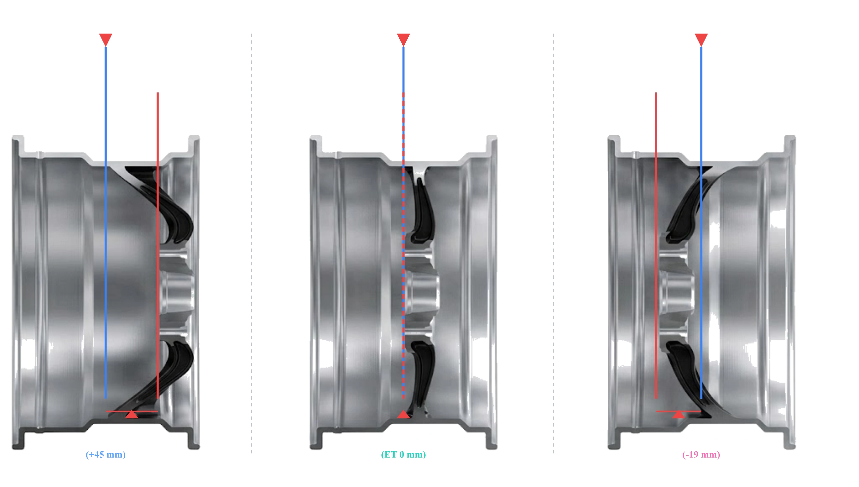
Wheel Offset, Backspacing & Frontspacing Geometry
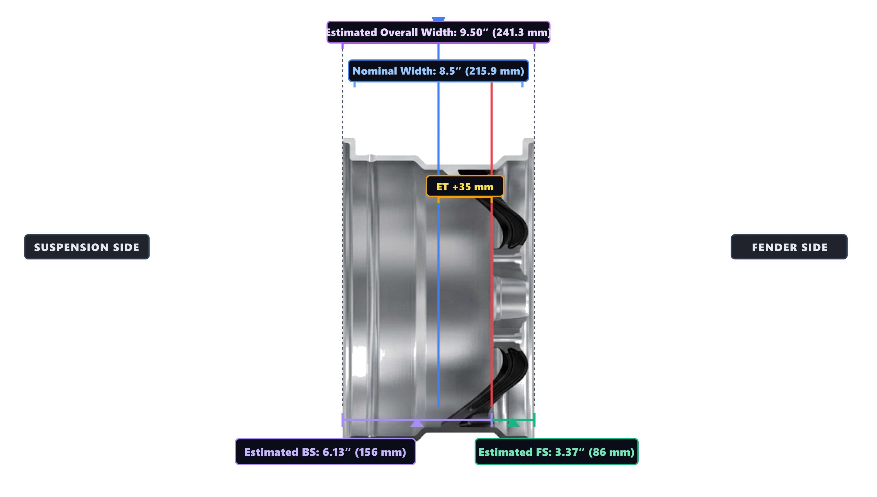
Backspacing and frontspacing are distances from the hub mounting plane to the inboard and outboard outer rim lips. When only nominal wheel width is known, the calculator estimates these distances using the conventional +1.0-inch overall-width approximation.
Wheel Width, Centerline, Offset, Backspacing & Frontspacing
Real-World Fitment Factors & Physical Limitations
The calculator calculates nominal wheel-position changes from wheel width and offset, but complete vehicle fitment depends on additional physical constraints:
- Brake Caliper Clearance: Brake-caliper clearance depends on wheel spoke and barrel geometry and cannot be determined from offset alone.
- Tire Section Width & Shoulder Bulge: Mounted tire width can extend beyond the wheel rim and depends on the tire, rim width, pressure, load, and manufacturer geometry.
- Scrub Radius & Steering Geometry: Changing wheel offset can alter scrub radius and therefore affect steering feel and load paths. The calculator does not model suspension or steering geometry.
- Standardized Bead-Seat Profiles: The Tire and Rim Association Engineering Year Book publishes standardized tire and rim information, including approved rim contours and dimensional data for the North American market.
Related Tire & Wheel Calculators
Looking to compare overall tire dimensions, speedometer calibration, or convert metric sizes to inches?
Frequently Asked Questions
References
- SAE International – SAE J1982_202303: Nomenclature - Wheels for Passenger Cars, Light Trucks, and Multipurpose Vehicles. Standardized engineering nomenclature and definitions for wheel offset, mounting face, and centerline.
- The Tire and Rim Association Engineering Year Book. The Tire and Rim Association Engineering Year Book publishes standardized tire and rim information, including approved rim contours and dimensional data for the North American market.